What are the jumpers and LEDs on the Tera2 PCoIP Remote Workstation Card used for?
All external connectors on Tera2 PCoIP host cards are for diagnostic purposes. Jumpers J15 and J25 are configurable and their functions are described below. If you want Tera1 jumper explanations instead, refer to What are the jumpers on the Tera1 host card used for?.
The diagram below shows the location of the jumpers on a Tera2 host card.

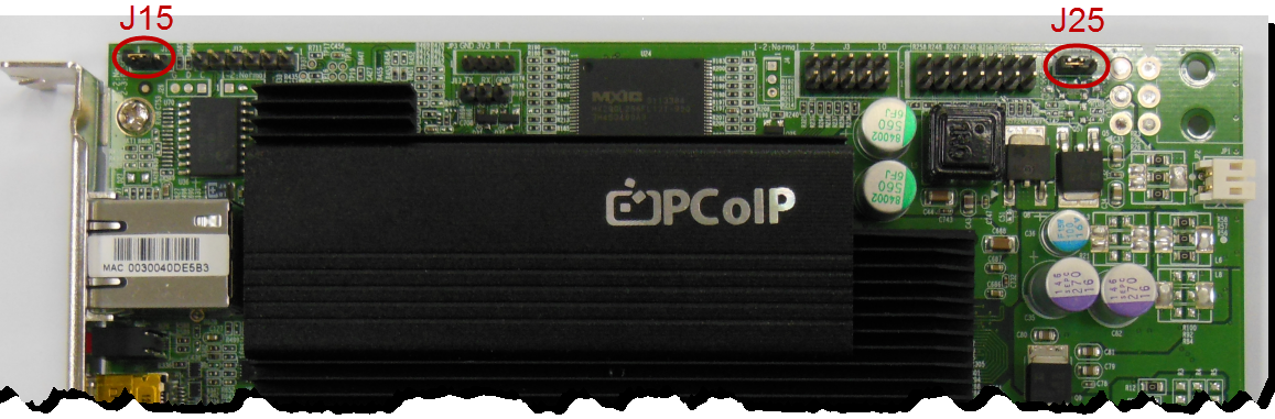
Jumper J15
This jumper will reset the host card back to factory default settings.
To reset:
- Place the jumper on pins 2 and 3 on a unpowered PC/host card.
- Power on the host PC/host card and wait until the heartbeat pulse is visible.
- Power down the host PC/host card.
- Put jumper back to pin 1-2.
- Power on the host PC/host card.
Jumper J25
Adjustment of the ground jumper is not normally required. The power button output from the host card is isolated so that it can be connected to the motherboard in either polarity. Some motherboards do not work with an isolated input and thus require the ground jumper to be installed. This is done by shorting pins 2-3 which requires the power cable to match polarity with the motherboard pins. When left on the default settings (pins 1-2 shorted), the polarity of the power cable is ignored as the power button is now isolated.
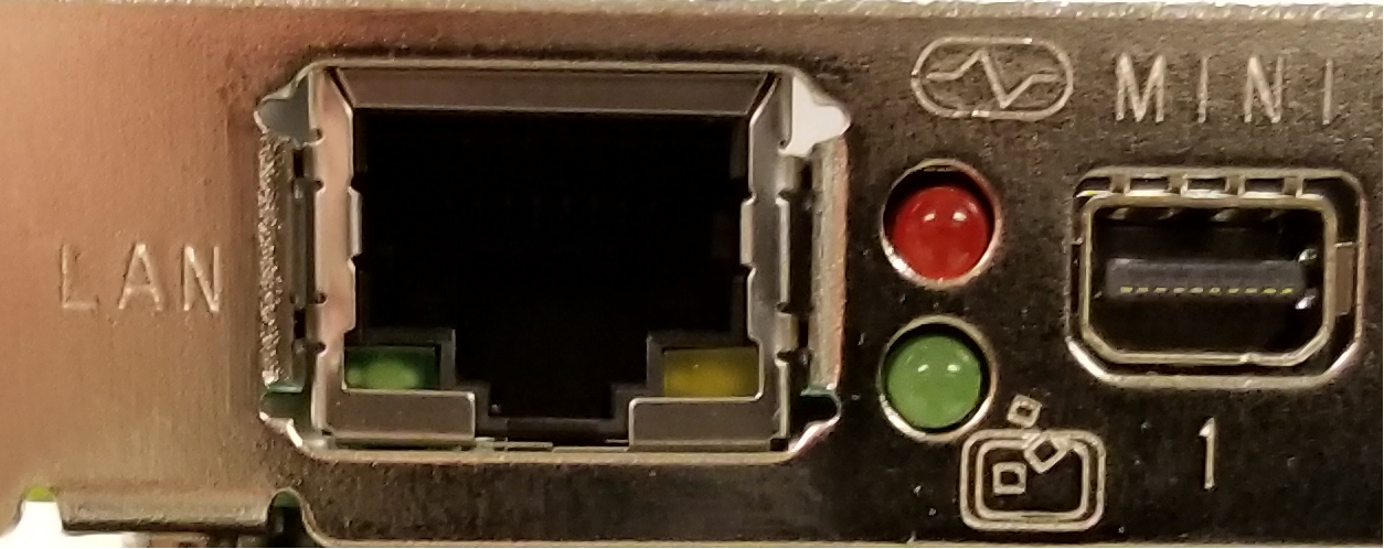
LED Indicators:
There are 4 LEDs on the back of the Tera2 remote workstation card, they serve the same purpose on both the 2220 and 2240 cards.
Red LED = Heartbeat, notice the heartbeat symbol. This LED will normally blink indicating normal operation
Green LED = Session, notice the PCoIP symbol. This LED will be solid green when in session.
LAN Green LED = Network activity, this LED will blink indicating normal operation.
LAN Yellow LED = Network connection, This LED is normally solid.

See also:
How do I connect the PCoIP Remote Workstation Card's power button cable?