How do I connect the PCoIP Remote Workstation Card's power button cable?
Review and carefully follow the steps below to install the power button cable. This allows you to use your PCoIP Zero Client to remotely power on (or off) a host machine that has a PCoIP Remote Workstation card (host card) installed.
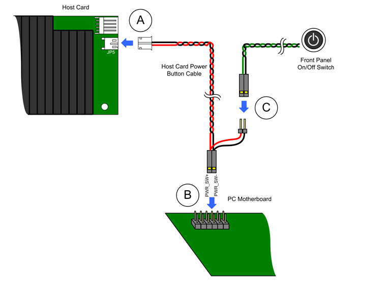
A. On the host card, connect the white end of the power button cable to the connector on the PCoIP Remote Workstation Card. The connector should be labelled either "JP5" (Tera1) or "JP1" (Tera2).
B. On the PC motherboard, locate the computer's front panel on/off switch cable. Disconnect the end of the cable that's attached to the motherboard and locate the power on/off signal pins. Connect the red wire on the PCoIP Remote Workstation Card power button cable to the positive terminal of the power on/off pin, and the black wire to the negative terminal. The negative terminal is typically a ground pin.
|
Please Note: The location of the power on/off switch pins will be different from one motherboard to another. See your motherboard user manual for details. The host PC/workstation will not power up if you have the connector inversely connected to the positive and negative terminal on the motherboard. Please also note that on Tera2 PCoIP Remote Workstation Cards, there is a grounding jumper (J25). This jumper generally isn't needed, but is sometimes useful in PCs where the remote power button does not function as expected. Units such as the Dell Precision rack mount workstations make use of this jumper to enable functionality of their power button when the power cable is connected to the motherboard through the special header. If the jumper is installed on pins 1-2, the polarity of the power cable is irrelevant; when on pins 2-3, polarity must be correct. |
C. If possible, connect the PC's front-panel on/off switch cable to the 2-pin header on the PCoIP Remote Workstation Card power button cable. If this isn't possible, the PC's front-panel on/off switch will be disabled.
The following diagram shows a typical configuration showing a 2-wire PCoIP Remote Workstation Card power button cable connected between the PCoIP Remote Workstation Card'spower button cable connector (A) and the PC motherboard's 2-pin power button header (B), and to the front panel on/off switch on the host PC/workstation (C).
Note: On a Tera1 PCoIP Remote Workstation Card, a jumper should be set to pin 2-3 of the Wake Configuration header when the power button cable connector is used. For more information, see What are the jumpers on the Tera1 host card used for?.
For further details on how the power button cable is used to support remote power management, please see: How does the PCoIP Zero Client/PCoIP Remote Workstation Card support remote power management?